Placeholder Image

字幕表 動画を再生する

  • So in a previous video we used an eeprom as a decoder for a seven segment display

  • so by hooking up a binary input here, so this is [6] or you know 4

  • 5 by inputting a different binary number on the address lines of the eeprom the eeprom would output

  • Ones and zeros in the appropriate places to turn on or off the appropriate segment on the seven segment display

  • But how can we build a decoder for [8] bits that outputs a number from 0 to 255?

  • on three of these seven segment displays and

  • That question came up in the comments on the video about using an e eeprom as a 7 segment decoder

  • the YouTube Cuber asked what do I do if I have multiple seven segment displays is flying one decimal number and

  • There's some good replies in here

  • So rest little teapot says if I've got this correctly you would need one e eeprom for each seven segment display

  • And that's exactly what what we've got here? We've got one e eeprom for each of the seven segment displays

  • So we've got a one place a eeprom for the one stage at a tens place

  • for the tens digit and a hundreds place

  • for the hundreds digit and

  • Then the address lines or at least the first eight of the address lines for the chips are all linked together

  • So if we put an address value on these eight lines here in this case

  • I'm putting that binary equivalent of 123 that same value is going to show up on each of these chips

  • So this chip is going to be at address 123

  • This chip is going to be at address 123 and the chip is going to be at address

  • 123 and so at that address for the hundred ship. It's programmed to display a [1] at that address for the tens chip

  • It's programmed to display a 2 and the ones chip is programmed to display a 3 and then they go on to [say]

  • Let's say we want to [represent] the numbers from 0 to 15

  • We can use 2 [e] [eproms] and this is this is exactly right here, so this shows for the address 0 through 9

  • That first the eeprom is just outputting all zeros and the second one

  • Outputs the numbers from 0 [to] 9 and then it wraps around here

  • And that first year you promised a 4 10 through through 15

  • And then Jason Masters here

  • [sort] [of] kind of restates that and then says

  • Yeah

  • if you link the address lines of the chips together so all the chips get the same address you put the binary number on the

  • address Line and

  • The output of the chips will display the decimal : that's that's a yes

  • That's absolutely right so simple

  • But then this is this is interesting the [YouTube] cuber again says another thing that I thought of is

  • multiplexing through the eeprom so you get the binary number and the digit number as input and

  • Then you get a you know binary coded decimal

  • or I guess you'd get the

  • Decoded set and segment [things] [as] your output and so you need a binary counter on the digit number input to [start] multiplexing

  • I like this idea rather than needing [to] have three of these [ee] problems one for each digit

  • We can do it with a single the eeprom that drives all three digits now

  • It's going to be a little bit more complex

  • But it's I don't think we're going to need to do anything that we haven't already done elsewhere in our computer build

  • So let's give it a try and I'll explain more about how those

  • Multiplexing works as we as we build out the circuit, so this display module is going to be part of our computer

  • It's going to [be] output for our computer

  • So I'm going to connect a new breadboard here right below the b register for a computer and build the display

  • Output here, and so we're going to use a single eeprom

  • that's the the idea of this multiplexing idea the 28 C 16 [I'll] start by connecting it to a

  • single [seven] segment display, and this is a

  • common cathode

  • Instead of common anode which were the ones we were using before so I'm going to connect the common cathode here to ground

  • through this 330 Ohm resistor and

  • There is the reason I'm using a common cathode

  • Display here which I'll go into later and so I'm just going to check the eight output pins for the eeprom to the seven

  • segments of the of the seven segment display plus the decimal point

  • And it really is just kind [of] hard to follow with everything on top of each other there

  • But basically what's going on is we've got these i/o pins [io0] [one] [two] [three] [four] [five] [six] [seven]

  • Those are the pins that are connected here, and they're connected to the seven segment display

  • basically like this

  • So you know this is what our seven segment display is going to do just zero through nine [since] we're just getting decimal at this

  • point and

  • each of the segments it has a letter designator, so

  • Abcde F and then g is the one in the middle

  • And then of course there's also the decimal point over here, and so this is the way that I've arranged the the bit order

  • So the decimal point is the most significant bit so that corresponds

  • With Io7 here, and then it goes

  • Abcdefg where g is the least significant bit corresponding with io 0 over [here]? So that's that's how I hooked this up

  • [but] of course you can hook it up any way you want you just got to make sure you know which bits need to be

  • On for each of the numbers that you [want] to display?

  • now we can also hook up power and ground for the eeprom so that [it's] powers and

  • Then the control signals that we've got we've got our chip enable our output enable and our write enable

  • And chip enable we want that to be active, so that's active low

  • Output enable we also want to be active, and that's also active low

  • and

  • Then write enable we don't want that to be active

  • We don't wanna be writing to this and so that's active low

  • So we want to tie that high so that we're not

  • Going to accidentally write anything to this chip and so that leads just the address line

  • So there's eight address lines over on this side, and then address eight nine and ten over on that side and for now

  • I'm just going to temporarily tie those all low

  • That's the first eight address lines are all tied low there and then I'll also tie the remaining three address lines over here

  • Low as well, so with all of the address lines tied low

  • This tip is going to be addressing address location zero and we'll see whichever bits are set on the output here

  • so let's add power and

  • We can see that. We're getting all the bits set so all seven segments plus the decimal point are on so

  • Address locations, they're on this chip is apparently programmed with with all ones and if we go to some other address so address one

  • Two so it looks like this chip is probably erased if all it's giving us is all ones on the output

  • So let's pull the chip out in and program with something

  • So I've got the eeprom in our Arduino programmer

  • And I'm going to come over to the code here and because we're using a common capital display now instead of a common anode

  • I'm going to make sure I've got the [right] programming for that

  • So this is the right bit that we want to have set for common cathode

  • so I'm going to add and upload that and I look at my serial monitor, and so it's programming and

  • Okay, it looks like it's going to start by erasing the eeprom and then it programs it and it looks like it's got that program

  • In there for the first 16 bytes okay, so let's pull it out and put it back in our other circuit

  • to put this back in here now and connect power

  • So now we've got a zero and if we go to address location one. We've got a one and

  • This is working as we would expect

  • but of course we want [to] have more than one digit and so [the] way the

  • Multiplexing is going to work is we're actually going to drive all the digits using the same data bits

  • And then we're going to switch on certain [digits] at certain times, which will hopefully make more sense in a minute here

  • So I'm going to add a couple more digits here

  • and what I'm going [to] do is I'm going to connect all of these essentially in parallel so that the outputs of the

  • Eeprom go to all of them in the same way

  • So I put all of the pinch of the [segments] together

  • [so] if we connect the common cathodes for each of these to ground we should see each of the digits light up the same way

  • Assuming everything is connected properly which

  • They're getting pretty crowded down here. So let me see what's going on here there

  • We go and so now if I change the input all three of these digits should change so there's one

  • three

  • Two and so on so of course this isn't what we want

  • But it does mean that we can control all of these digits from the one chip

  • And actually I've got a little extra room over here

  • So I can add a fourth digit if I want and I think there might be a way to use it

  • Because I think there will actually be a use for that fourth digit, which I'll get into later

  • but

  • now what we need to do is build the

  • Multiplexing logic that cycles through each of these digits so we can display a different number on each digit and the sequence that we need

  • a clock and I don't want to use the clock that is running the rest of the computer because

  • We might want to run that it if different rate or whatever so I'm going to build a separate clock just for the output display

  • using a five five five timer

  • Let me connect a five five five timer over here. I'll connect ground and power

  • And then I'm going to connect a 2 micro Farad capacitor from pin two to ground

  • I'm also going to connect 10 2 over 2 10 6

  • 10 [five], I'm going to connect to ground with a 10 nano farad capacitor

  • and I'm going to put a 100k resistor between

  • thousand six and seven and then a 1k resistor [between] 10 seven and and five volts

  • between 10 seven and eight I guess

  • [10/8] is already connected to [five] volts

  • And so this is a simple a stable configuration

  • For the five five five timer and if I hope the the output which is pin three up to an led

  • Which is going through a resistor to ground. I should be able to see this pulsing so I connect power

  • There we go, so we have a little clock running here

  • And so next what we want to do is we want to use this clock to sequence through each of our displays and to do

  • That what we need is a small counter, so the 74 LS. 76 has got two Jk. Flip-flops on it

  • Which is just enough to make a simple two bit counter and we basically want to take [advantage] of the toggle

  • Functionality of the Jk. Flip-flop to build a simple counter so we want to basically just connect the preset clear J

  • And K inputs all high and then just use the clock every time the clock pulses

  • [we'll] get a toggle and we can use that [to] build a counter

  • So this is the preset and clear for the first

  • Flip-flop tying both of those high as

  • Well as the J input and the k input

  • Those are all tied high and then also the preset and clear for the second flip-flop

  • As well as the J and K inputs for the second flip-flop

  • and then of course this chip also needs power and

  • ground to power the chip so next we can connect the clock into our clock input for one of our flip-flops and

  • Then we'll connect the output of that flip-flop

  • into the clock input of the other

  • Flip-flop to create a counter so we'll connect the output of our five five five timer to that clock for one of the Jk flip-flops

  • And I'll connect an [led] to the output of that flip-flop and also connect the output that flip-flop around to the clock

  • for the other Flip-flop and finally I'll look at the output of the

  • [second] Flip-flop

  • So now if we power this up, hopefully, we'll have a working counter

  • And it looks like we do so we've got this counter now

  • So counting from zero one two three zero one two three

  • So that's counting from zero to three and so we can use that count to control which of our digits

  • We want to display to control that I can use to these additional address lines

  • So remember we've got our eighth address lines down here that we're using to put which value we want to show so right now

  • We're inputting a [2] and we're seeing twos

  • But we've also got these three additional address lines up here that we're not [using]

  • They're all tied to 0 we can tie two of those to these these counting

  • leds over here

  • So instead of tying this address line to ground I can tie it to this

  • Led here and instead of tying this to ground I can tie it to this led over here and

  • What you see is that when both of these are 0 we see the same thing? We saw [before] we see that [2]

  • So once every 4 clock cycles essentially we get a 2 here and then the other times

  • We're getting just all eight with the dots so basically all all of the bits are set

  • But what we could do is program this so that when the counter is at 0?

  • It's outputting the number we want in the ones place and when the counter is [1] it's outputting the number we want in the tens

  • Place and when the counter is 2 it's outputting the number we want in the hundreds place

  • So let's go ahead and actually program the eeprom to do that so again

  • I'm going to put the eeprom into our arduino eeprom programmer, and so just to summarize what we're trying to do here. We've got these

  • 11 address bits

  • and

  • We're using the bottom eight of them a 0 through a 7 to input the number that we're trying to display

  • so this could be anywhere from all zeros all 1 so 0 to 255 and

  • Then we're using address 8 and address 9 to tell us which digit we want we want to display

  • So if these are both zeros and we want to display the ones place

  • and so if we put in for example if we put in the number 123 here, we'd want the output to display a 3

  • but if we set a a high if we put in 0 and a 1 for a 9 and a 8

  • Then we want this to display the tens place for that same number so again if we've got 123 let's say here

  • Then we want to display [a] 2 so that would be the tens place

  • and

  • Then if a 9 is a 1 and a 8 is a 0 then [we'd] want to display a hundreds place for whatever is in

  • Here so again if this is 123, [we'd] want to display a 1 so again just as an example here

  • This is what we would actually want to see programmed in the eeprom for example

  • so at address 0 0 0 and then this [0] 1 1 1 1 [zero-one-one], this is this is the binary for

  • 123 in decimal and

  • So because we've got [two] [zero] [zero] here

  • the output is going to be the bits that we need to set in order to show a 3

  • But if our input is that same set of bits in the lower eight bits, so this is still representing the number 123

  • but in this case if we've got a [0] [1] in these upper bits

  • Then we want to output something different one output the bits that we need in order to display the number two on

  • [the] 7-segment display, and then same thing here for the hundreds place if a nine is one and [eighty-eight] is zero and

  • The rest of these are the same this is still representing the number 123

  • Now we want to output whatever we need to output to display the number one this case is just these two segments

  • And then you know because we've got four digits. There is also this case

  • We have to handle where we've got a 1 and a 1 in a 9 and a 8 and in this case

  • We'll just output nothing so all [zeros] will just mean none of the [segment's] are on so that fourth display

  • I'll just be blank, so this is what we want to program

  • So we don't really want to just type out all [of] those because that's that's going to be you know over a thousand

  • Separate numbers, and we don't want to we [don't] want to type all that out like this

  • so let's write some code that actually just fills in all of the numbers that we need to program into the eeprom so I am

  • Going to use this this part here at least up [to] number nine. Yeah, so this this part here

  • I'm actually going to copy that and then we'll comment that out and then down [here]. Let's see

  • We don't need to erase the whole eeprom

  • we're just going to be writing over a lot of this anyway, so I'm going to delete this code and

  • Then here when we program the data bytes rather than just programming whatever was in that Data array

  • [we] call this digits

  • and

  • so these are just the the hex codes that we need in order to display each of the digits from from 0 through [9] and

  • So we want to start by programming all of the ones place so we can go from address

  • 0 to 255 and we'll do right right [eeep] rom address and

  • then we

  • [want] the the digit that corresponds to the ones place for that address so to get the one place of the address we can do?

  • address Mod 10 and this % is the Modulo operator which

  • Essentially just divides a dress by 10 and gives you the remainder, so if a dress is 0 we divide by 10

  • the remainder is 0 if

  • the

  • address is

  • 123 we divide that by 10 we get 12 with a remainder of 3 and so it'll you know so this will give us 3

  • Which is the ones place in 123 so this will give us whatever the value of the ones place is for a dress

  • But we we don't want to write that we want to write the the digit for that

  • So what we can do is we can just use this as an index into digit

  • so if we say digit

  • and then at that index because this

  • This address mod 10 is always going to be a number between 0 [and] 9

  • Because whenever you divide something by 10 the remainder is going to be between 0 [and] 9

  • So that's always going to be a number between 0 9 and so that's just going to give us whichever of these values

  • Corresponds with that position

  • So this should write all [of] the ones places to the [eprom] next we need to write all the tens places

  • So we'll go from 0 to 255 actually address is probably not the best name for this let's call this value

  • Because the value in the address are only the same for the ones place

  • So I'll just rename all these value to be consistent and so here

  • We're going to write to value Plus

  • 256 is

  • The address that we're going to write to and that's because we're doing this case here where we're doing the the tens place and so

  • a 8 is always going to be set and the value the place value of

  • This bit is 256 so it's going to be whatever the value is plus

  • 256 and that's the where we want to program the tens the you know [does] [a] appropriate code for the tens place

  • And so here we want to get the tens place

  • And so if we do address or not address value oops actually this [should] be value mod 10, so if we do value

  • Divided by 10 because value is declared as an integer here this divided by 10 will be an integer division

  • So it won't give us a decimal place

  • It'll just give us a truncated value

  • so if it's 123 and we divide by 10

  • If these give us 12 it won't give us 12 point 3 and so if we take that and then we do a mod 10

  • We'll get the 2 for the tens place and so again

  • we can use that as an index in two digits to get the

  • appropriate code to display that digit

  • So we'll write that and then we want [to] do the hundreds place, and it's going to be the same thing

  • So we'll just go through all

  • 256 values in this case

  • they offset as 512 because we're writing now to this range here where a nine is set in a eight is not set and

  • The place value [of] in binary of a nine is 512 so we just make sure [we] just add that to whatever our value is

  • To put it in that address

  • So value Plus 512 and then digit we're going to index into digits for value

  • Divided by 100 to get to hundreds place and then mod by 10 although that's probably not going to be necessary because we're only going

  • from 0 to 255 so this should only be 0 1 or [2] but we can do that anyway for consistency and

  • So this will write all the [hundredths] place and then for that fourth digit because we do have four digits

  • We just want that last one to be blank so we can do a loop that [just]

  • Writes all zeros to that range, so this will be value plus

  • 768 Because both A

  • 9 and a 8 are set so you take the 256 plus the 512 and you get 768 and

  • Then for that whole range. We're just going to write all zeros because we don't want that digit to display anything

  • we'll just write all zeros and

  • We don't need this loop to write our data

  • So we'll do that, and then you know we can still print the output there

  • So let's upload that

  • and it's programming and it's done and

  • Well, we just printed the first 255 bytes here, but you can see this should just be repeating the [first] 10

  • Things over and over again, it looks like it. Maybe is but yeah, let's give this a try

  • Let's pull this out and put it into our

  • Circuits we get the eeprom back in the circuit hook up power

  • And we see [it's] cycling through to zero and blank but of course it's not putting the numbers on to the individual displays

  • It's just showing them in sequence. Which is not quite what [we] want, but we're getting there, and so if we give this another

  • number so let's say we give it that example like [that] 123 and you see three [two] one blank three two one blank and

  • So what we want is we want the three here the tool here the one here and the blank there

  • So what we need is some way to sequence through these

  • Displays and for that what I'm going to do is I'm going to use our

  • Counter to then feed into a decoder so to do that. I'm going to use the 74 LS

  • 139

  • Which is a two to four line?

  • decoder or D multiplexer and so what it does is it's got two inputs say 1 and b 1 and

  • Depending on what those values are you get one of these data outputs?

  • Goes low and so basically you can imagine just this a and B

  • We're going to use our

  • counter here which is counting from 0 through 4 and I nari we're going to use that a and B and

  • It's going to cycle like this from both being low to a being high then b

  • Then both so that's what we've we've already got that [and] then what happens is the outputs it just cycles each of these

  • Going low in turn so just cycles to each of those and then what we can use this to do is is select which

  • Output digit, we're displaying, so [the] way this chip works is pretty simple

  • It's got the two inputs and it's essentially just using a series of [an] gates and inverters

  • To pick based on how these inputs are set which output to turn on

  • So if we put with 74 or less 139 up here, it's pretty simple to hook up

  • We just need to give it power and ground like we do with all [of] these and then it has an enable pin here

  • Pin 15 that's active. Low, so we want that to [be] active. So we'll type in 15 here to ground and

  • Then the inputs are just [pins] 14 and 13

  • And I'm just using the top one because we're coming from from over here

  • So stay on that side of the board so I'll just hook these two

  • To those inputs so now let's take a look at the outputs which are on pins 9 10 11 and 12

  • And so you can see the outputs of this decoder

  • You've got all of the outputs on except for one and the one that goes off corresponds to our input as we're counting

  • This is very convenient and [is] also the reason that I used the common Caso displays

  • because

  • what we can do is we can hook these outputs up to the cathodes here rather than just [hi] all the cathodes to ground and

  • That way the only cathode that will actually be hooked to ground

  • Will be the one that we want to be displaying for example instead of connecting the ones place

  • Cathode directly the ground to this resistor if I connect it to this first

  • output here

  • You'll see the ones place is only on

  • When we're displaying that three and the three is what should be in the ones place, [so] in other words

  • we're both displaying the correct digit and

  • Putting the correct address into the eeprom to display that place value at the same time and so I can do the same thing for

  • the tens place instead of connecting that directly to ground

  • through that resistor I can connect it to

  • the second

  • sitting here

  • And so now you see the one the tens place only shows up when we have a two there and remember the input here is

  • is 123

  • So we get the two in the tens place?

  • We get the three in the ones place just as we should and then the hundreds place

  • Same thing rather than connecting that directly to ground we can connect it to this place here, and so now we only see the one

  • When we're addressing the location in the eeprom for the hundreds place, and then finally [this] fourth digit

  • We can do the same thing although

  • We shouldn't see much there because remember we programmed all zeros

  • Into that last block of memory and so now we've got the right digits in the right places

  • but this isn't quite what we want right because we want our display to actually show us a

  • Number we don't want to have to read it like this

  • This is kind of kind of Janky, but [what] we can do is adjust the speed of our clock

  • and so if I replace the 100k resistor with a 100k potentiometer [I]

  • Can start to increase the speed by turning that potentiometer?

  • And what you'll see is as it gets faster and faster

  • it looks more like 123, and if I go fast enough

  • You can't even tell that it's flashing like that

  • So that's basically our display now instead of sticking this pot in here. I'm going to put the hundred K resistor back

  • So now another way to slow this down is instead of using this 2 Micro Farad capacitor. I'm going to replace that

  • With a 10 nano farad capacitor instead and that's going to give us a similar kind of effect and with it running this speed

  • We don't really need any of these leds. They're not showing us anything interesting so I'm going to pull all those out as well

  • [I'm] also going to clean up these wires here and just replace them with wires that are cut to length

  • And so there we go

  • We've got our 8 inputs here

  • and we can switch these two different values and

  • We get the decimal representation of whatever input is down here on our display

  • Now we've also got this last address line that

  • We could do something interesting with so right now if we take that [high] we just get all ones on everything because we haven't programmed

  • The other half of this chip so we could actually have two different

  • types of display we could program the first half of the chip the way we have four decimal display and

  • Then the second half of the chip could be programmed with some other kind of display

  • It could be hexadecimal if you want to do that

  • or

  • What I think would be interesting [and] since we have this fourth digit is

  • You could program the second half of the chip to show negative numbers or more specifically you could you could have a decode two's complement

  • numbers which could be positive or negative two's complement uses an 8-bit number to represent numbers from between

  • Negative 128 up to a positive 127 and [so] we can use this first digit to show the negative sign if we need to

  • So to display in in two's complement. We want to basically do the same thing, but instead of

  • Right now we're programming values from the Rivermen memory locations essentially from 0 through

  • 10 23 because this is going to be 255 plus 768 10 23

  • So we're programming simply the whole first half of the chip with our normal

  • Unsigned integers and so for the signed integers that use the two's complement. We're going to start at

  • Memory location 1024 so to program that we're going to want to go value from negative

  • 128 oh you know what I just realized we might have a bug because look at this we're going from zero [to] values less than

  • 255 so we might not actually be programming

  • 255 so let's let's actually give that a try. Let's go back here

  • Set this to here and let's try looking at position 255. I bet it's not programmed properly

  • so if we go to

  • Let's see that's 254 and if we change this to 1. Yeah look at that. We didn't program 255 because

  • we said less than

  • 255 so we need to do less than or equal to for all of these

  • I'm glad I caught that

  • Now if we come back down to here so our value is going to go from Negative 4 to

  • [complement] our value is going to go from negative 128 to positive 127

  • and

  • again

  • Our our address is going to start at 1024

  • [but] we don't want to add value to it right because values start to negative 128 so if we add that to

  • 1024 we're actually going to be writing

  • [partway] into into this

  • Area before so what we can do is we can take

  • Value and cast it to a byte. So what this will do is it will take

  • Value and treat it as an unsigned byte

  • So it's if value has negative 128 in it then this will say well negative 128 is represented as a byte as 1

  • followed by seven zeros because that's how

  • yeah, because this is going to use two's complement to represent that so this should take value and and

  • Using a tooth compliment convert it to an 8-bit byte

  • Which which should be a positive number?

  • And then we'll use that as our as our address and then what we want to write there is

  • Essentially the same thing as we have here digits

  • For value Mod 10, but what I want to do is I want to take the absolute value of this

  • So if it's you [know] that's negative 123 then this will take the absolute value of that and give us

  • 123 and before we mod by 10 and look at the last digit if now I can move on to the tens place again

  • It's going to go from 128 to 120 or negative 128 to 127 and basically the same thing

  • But of course we're going to divide value by 10 first 2 gets tens place and our base here instead of being

  • 1024 is going to be 12 8 right it's 1024 plus 256 and then for our hundreds place

  • We can just copy this again, and so this will be divided by hundred to get our hundreds place and this will be

  • 1280 Plus 256 which is

  • 1536 and so that'll be our hundreds place

  • And then we just need to do that fourth digit there which before we just set all [zeros]

  • But in this case we could use [that] to

  • Represent our sign by setting a negative sign there until we want to do is if if our value is negative

  • so if value is less than

  • Zero, so if it's negative then we want to write to our address

  • so take value and cast it to a byte to get a positive two's complement representation of our value and

  • Then here are off that's going to be 1536 plus 256 which is

  • 1792 and so if it's negative we want to write

  • a believe a 1 right, so one should be

  • This should be the one

  • That last bit should be segment g which which is the one in the middle that would look [like] a negative sign?

  • and

  • Otherwise if it's Nonzero we want to write to that location plus

  • 1792 in [this] case we [just] want to write [0] we want to display to be blank if it's positive

  • [and] I think that should do it

  • Yeah, and I'm going [to] add one of the things. I'm just going to add some

  • Some print lines here so we can just keep track of what it's doing well

  • It's programming because it's programming the entire a eeprom where we're programming all all

  • 2048 memory locations into CD promised over it's going to take a little while

  • So I'll add these print lines so that it's easier to see what's going on [ok] so

  • that should be it, so let's go ahead and

  • upload this

  • Ok our serial monitor, and this is taking a little while speed this up for you, and it's done

  • So let's pop the eeprom back in our circuit here, so if you got our 255 here

  • So that's fine, and so this should work [just] just normally so you know if we set some other values here

  • 127 Or you know 123 122

  • 123 so this is this is working normally

  • And these values obviously are lower than 128, but if we go up to you know 251 that's going to be positive

  • [so] because we've got this bit low, but [if] we want to look at our two's complement, and we set this bit high now

  • We're looking at two's complement. So anything below

  • 127 Or 128

  • should be the same so any of these other values should be the same if we set this high bit now to

  • Something now. We've got a negative number, so this is negative 13

  • So let's see if we're in binary and we put in 1 1 1 1 0 0 1 1 in binary

  • We convert that to decimal we get 243 and so that would be normally what it is

  • So if we go to our normal mode so yeah, that's 243 if we go to two's complement

  • Yeah, negative 13 so that's right. So we are getting we are getting the right thing

  • And we can try some other things let's just I'm just going to move these around to just sort of some random

  • Things we've got negative 46 in there. I don't know negative 62 let's say

  • so this is

  • 1 1 0 0 0 0 1 0 so

  • if we go to decimal yep, negative 62 and then if we're in unsigned mode

  • That should be 194 [yep], so it looks like this is programmed right and working now

  • We've got an option where if we set this low

  • We have a normal sort of unsigned mode, so this this will just represent numbers from 0 to 255

  • But if we set this high then our output will show us numbers from negative 128

  • Up to 127 and depending what we're using the computer for we may want one of those

  • Output modes or the other and we can set that using this this input here

  • So I [think] they're pretty much does it for our 8-bit display here

  • so we've got [8] bits coming in and we're able to display it either is a

  • Signed two's complement or unsigned and we did it with only a single 28c 16

  • ye prom So I

  • think that's quite an improvement over the last time I built one of these where I use three of these one for each digit and

  • we've got a

  • Two's complement signs mode as well

So in a previous video we used an eeprom as a decoder for a seven segment display

字幕と単語

ワンタップで英和辞典検索 単語をクリックすると、意味が表示されます

A2 初級

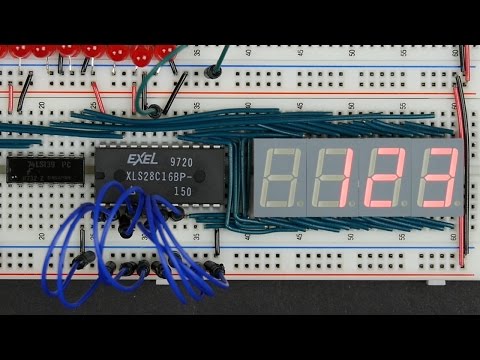
8ビットコンピュータのための8ビット10進表示を構築する (Build an 8-bit decimal display for our 8-bit computer)

  • 1 0
    林宜悉 に公開 2021 年 01 月 14 日
動画の中の単語